In order to externally power the engines I’ll use a 8-battery rechargeable pack that I bought long time ago for a led strip. This pack offers 1.2*8=9.6V and 2.3mAh when it’s totally charged. I welded a power jack plug to power Arduino, but it’ll be more helpful powering batteries, so I grabbed a male power jack to connect it, the protoboard will be connected with 2 stripped cables.
The scheme will be this one reported in this arduino forum https://forum.arduino.cc/index.php?topic=256290.0. He says that it’s not working, but it’s working perfectly for me and it seems that the transistor and diode are not heating up, so I’ll go ahead with this to test 😀
The code will be similar to the one in the pdf from the 17th exercise in the Arduino starter pack that I’ve used in previous iterations. It’ll just change the engines speed by emitting values (from 0 to 254) through serial port.
//Global variables
int motor1Pin = 3;
int motor2Pin = 5;

//Initial setup
void setup()
{
  //Initializing output
  pinMode(motor1Pin, OUTPUT);
  pinMode(motor2Pin, OUTPUT);

  //Begin serial port communication
  Serial.begin(9600);
  while (! Serial);
  Serial.println("Speed 0 to 254");
}

//Main loop
void loop()
{
  if (Serial.available())
  {
    int speed = Serial.parseInt();
    if (speed >= 0 && speed < 255)
    {
      analogWrite(motor1Pin, speed);
      analogWrite(motor2Pin, speed);
    }
  }
}
So I already have 2 wheels running, now it’ll be great to be able to change the direction to go backwards, I could achieve it by using the L293D chip that I got in the Arduino starter kit, so that will be the next iteration
With the PN2222A transistor issue solved I was finally able to start programming, that was what I was looking for initially. I added one wheel to the engine and checked the voltage (4.54V max with a 1KOhm resistance). It’s really slow, this won’t move the whole car kit (500g).
I followed the scheme from the project 17 in the pdf included in the aliexpress Arduino starter kit that I talked about in the previous iteration, but I changed the order of base, collector and emitter this time in order to fit my special transistor. As it was more or less working, I added another wheel and another circuit with another transistor to move it.
With just one wheel it started to move at 1.5V, equivalent to 100-110 value by PWM, but when I added one more wheel it needed twice the voltage, so I tried with 200. When moving two wheels at the same time it didn’t have enough power, so I created this program to alternate first one wheel and then the other. The exact behaviour would be: first wheel starts moving from 120 to max (254) within 5 seconds, it will keep this speed for 2 more seconds, then this wheel will stop and the next wheel will repeat the same process, starting all over again when this second wheel will stop.
//Global variables
const int motor1Pin = 3;
const int motor2Pin = 5;
const int maxSpeed = 254;

//Initial setup
void setup()
{
  //Initializing output
  pinMode(motor1Pin, OUTPUT);
  pinMode(motor2Pin, OUTPUT);
}

//Main loop
void loop()
{
  accelerate(motor1Pin, 120, maxSpeed, 5); //Accelerate the motor 1, from 120 to maxSpeed in 5 seconds
  delay(2000);
  analogWrite(motor1Pin, 0);

  accelerate(motor2Pin, 120, maxSpeed, 5); //Accelerate the motor 2, from 120 to maxSpeed in 5 seconds
  delay(2000);
  analogWrite(motor2Pin, 0);
}

//Accelerate the motor from currentSpeed to maxSpeed in n seconds
void accelerate(int motor, int fromSpeed, int toSpeed, int sec)
{
  int initialFromSpeed = fromSpeed;
  for (; fromSpeed <= toSpeed; fromSpeed++)
  {
      analogWrite(motor, fromSpeed);
      delay((sec * 1000)/(toSpeed - initialFromSpeed));
  }
}
Well, it works, but it doesn’t, in the next iteration I’ll power the engines separately so Arduino will only change the transistor bases.
I almost abandoned the whole project in order to come back to my world of ones and zeros where EVERYTHING WORKS. It seems that my PN2222A transistors are from a rare manufacturer who is not respecting the datasheet because the emitter-base-collector has other order, but first things first.
Right after having the car kit mounted, I tried to move a wheel with a transistor powered by the Arduino. To do so, I checked many schemes, but in all of them it was always the same: the engine was always at full speed, not being affected by the base pin, no matter if it was ground, 5V or PWM. I tried everything:
Schemes where the order with the flat side up was emitter-base-collector, like the one in the exercise 17 from the pdf included in the Arduino starter pack that I bought to my father. By the way, in the PN2222A datasheet the order is emitter-base-collector.
Schemes with a 2N2222 transistor where the order was collector-base-emitter (link here).
I tried more stuff that I can’t and don’t want to remember, I just didn’t care anymore.
A lot of things could have been failing or burnt, so I started checking from scratch to find the source of the problem. I learned a lot about transistors with this web and after 2 sheets of maths I understood much better how it should work. I also tested a basic PWM circuit to power a led in order to discard that the PWM, 5V or GND pins weren’t working anymore, luckily that was not the case, so the problem was not in what I was sending through the transistor base.
When everything was lost I researched how to check if a transistor was burned. I found some websites saying the same: if you put a voltmeter lead in a pin and you check resistence to the other two pins getting values different from “Over Limit”, then this first pin was actually the base. I made every possible combination and there was no doubt: the base was in the first pin!, also according to this website, the transistor was PNP.
Conclusion: the datasheet says that PN2222A transistor is NPN and the order is emitter-base-collector, but the PN2222A included in my Arduino starter pack is PNP and order base-collector-emitter.
In the next iteration I’ll finally manage to freely move the engine.
This is my first big project with Arduino. After so many doubts regarding which version to buy: 2 wheels, 4 wheels or even not touching anything related to Arduino at all, I finally chose the 4 wheel kit because the 2 wheel kit seemed ugly to me xD. I needed a few days to realize that the 4 wheel kit has almost everything to mount 2 robots with 2 wheels (just missing the idler wheel), so I think this is the best option with the future in mind.
2WD car kit
4WD car kit
This kit contains only basic car elements and a battery pack, but no electronic stuff at all:
4 plastic wheel with rubber
4 DC engines model 130, 3-6V and 70-250mA
4 plastic discs for the velocimeter (missing the led-photoresistor system to measure the light coming through the slots)
2 strips of 4 wires each to connect the engines
1 battery pack to group 1.5V batteries, 6V in total
2 methacrylate boards to sustain the components
8 clamping elements for the engines (2 for each engine)
Screws, nuts and metalic spacers to secure all components
What interests me is to control the software of what I could think of, the electronic part is a mere formality (unpleasant for me) so I’m counting on two engineers: my father and cousing. I’ve electronic notions from my engineering degree and my father, but he’ll be the one who will prevent me from frying more components than I should. This project is highly scalable: first of all achieving the car going forward with an acceptable speed. I could then add more features like turning and changing the direction. When all this basic stuff will work, it would be interesting to also dig deep into:
Adjusting the basic control. Calibrate wheels so all of them run at the same speed by applying different voltage to each one, since real life is not as perfect as the designs and there will be frictions and different weight loads between wheels.
Add more features. Remote control with bluetooth/wifi. Ultrasonic sensor with a servomotor to analyze the environment in front 180 degrees. Wifi camera to be accessed by the smartphone. Homemade Roomba with environment mapping.
In the next iteration I will (or try to) move one engine with a transistor powered by 5V from Arduino.
– Installing Apache with the following commands: sudo apt-get update
sudo apt-get install apache2
In order to check if Apache is working, we can open a browser and load the port 80 from our Raspberry Pi (in my case http://192.168.1.20).
– Installing php with the following command: sudo apt-get update php5 libapache2-mod-php5
We can check if PHP is working by creating the following file and accessing it through a browser (in my case http://192.168.1.20/index.php). echo "<?php phpinfo(); ?>" > index.php
sudo mv index.php /var/www/html
– Installing MySQL with the following command: sudo apt-get install mysql-server mysql-client php5-mysql
In order to check if MySQL is working, we’ll type the following command and we’ll login with the password that we chose in the installation process: mysql -u root -p
now inside MySQL we can list all databases with: show databases;
exit
– Installing phpmyadmin with the following command: sudo apt-get install phpmyadmin
In order to check if phpmyadmin works, we’ll add the following line: Include /etc/phpmyadmin/apache.conf
to apache2.conf, with the following command: sudo nano /etc/apache2/apache2.conf
and we’ll restart apache2 service: sudo /etc/init.d/apache2 restart
We can now query databases by accessing “phpmyadmin” through a browser (in my case http://192.168.1.20/phpmyadmin)
I’m going to explain how to install and configure a shared folder hosted in our Raspberry Pi to be accessed from our Windows PC by using Samba.
Installing samba packet by typing the following command: sudo apt-get install samba samba-common-bin
Creating a backup for the configuration file: sudo cp /etc/samba/smb.conf /etc/samba/smb.conf2
Editing smb.conf file: workgroup = <WorkGroup>
wins support = yes
read only = no
Folders at home are shared by default, but if you want to add another folder, you’ll need to add the following lines: [home]
comment = Home at Rasp3
path =/home/pi
browseable = yes
writeable = yes
only guest = no
public = no
Adding a password for the user pi: sudo smbpasswd -a pi
Restarting the service to load the new configuration: sudo /etc/init.d/samba restart
Sometimes we got problems when resolving DNS because some app is messing around. We can check the DNS server list with the following command: cat /etc/resolv.conf
We can add Google servers to resolve DNS to ensure that the conection issue won’t be related to DNS anymore. sudo nano /etc/resolv.conf and we’ll add nameserver 8.8.8.8
To keep discarding connectivity issues, we can ping Google (ping google.es) and it should be resolved with the servers we just added. But if we’re not even getting response to ping 8.8.8.8 that would mean that we don’t have access to internet. To also discard a wiring issue, we’ll ping to the nearest local ip (router is usually 192.168.1.1)
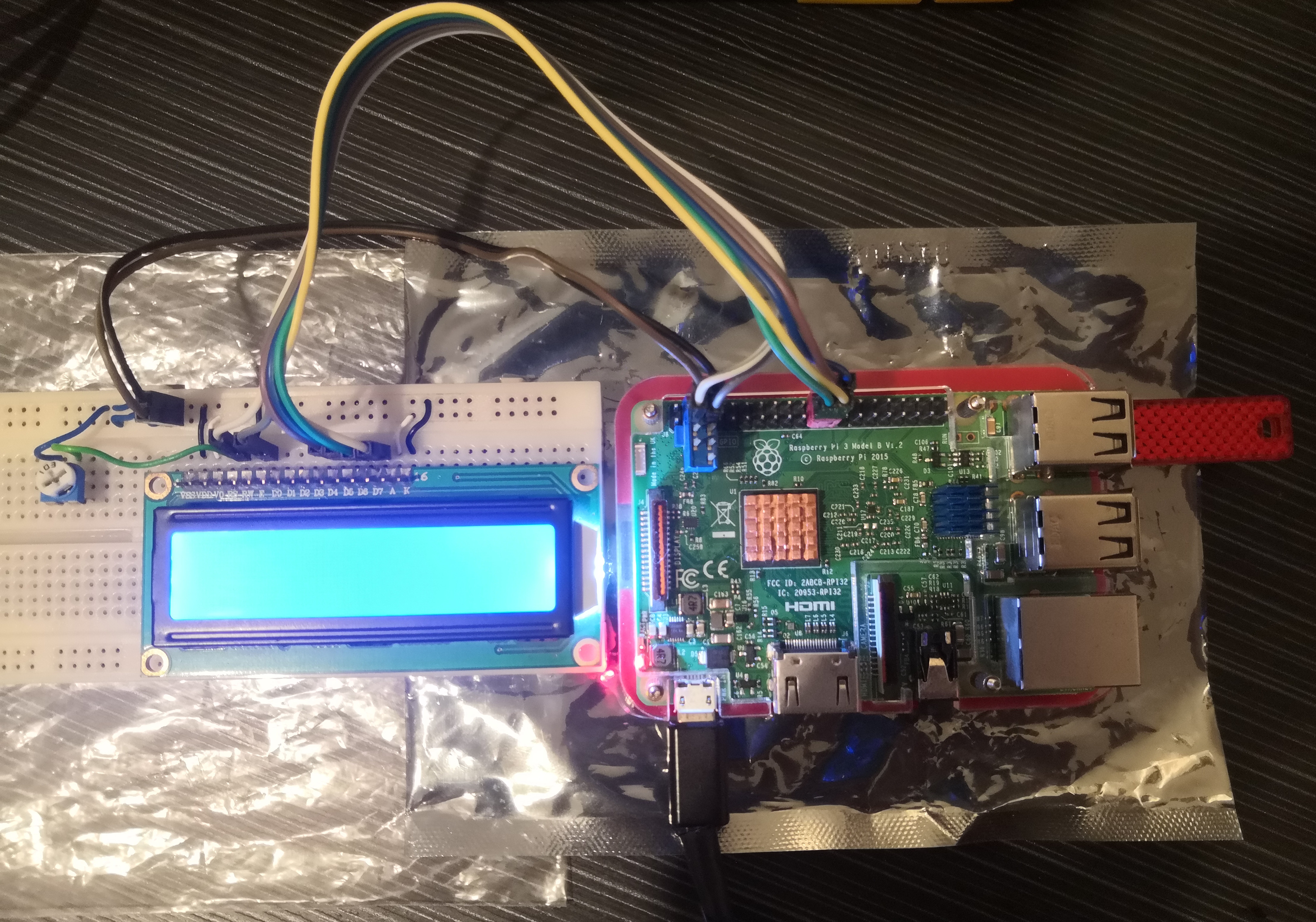
En este proyecto voy a controlar una pantallita LCD HD44780 para mostrar un texto scrolleando.
Necesitaremos, a parte de la Raspberry Pi, lo siguiente:
LCD HD44780 o similar (habría que adaptar el pinout si usáis otro)
Placa board para sostener los componentes
8 cables con pines hembra-macho de colores
Varios trozos de cable para puentear
Potenciómetro 10k Ohm (103) o resistencia de 470 Ohm (opcional)
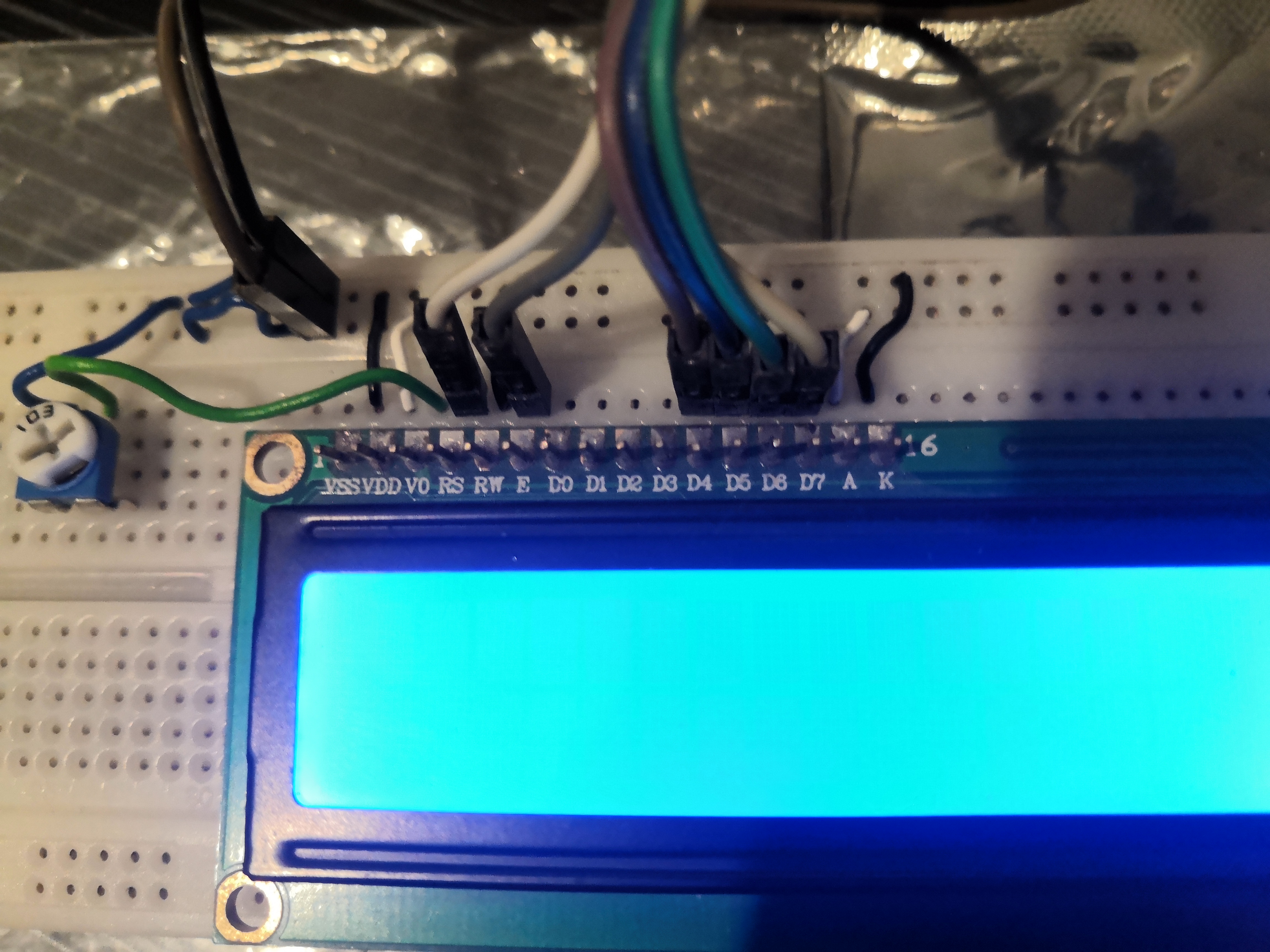
El LCD HD44780 tiene 16 pines (Vss, Vdd, V0, RS, RW, E, D0, D1, D2, D3, D4, D5, D6, D7, A, K) y usaremos la siguiente asignación de pines:
Vss hacia GND
Vdd hacia +5V
V0 hacia GND o hacia la patilla negativa del potenciómetro si lo usamos (la otra patilla del potenciómetro iría a +5V)
RS hacia pin GPIO2 para conmutar entre enviar comando o enviar dato
RW hacia GND porque solo vamos a escribir en el LCD, nunca a leer
E hacia pin GPIO3 para habilitar/deshabilitar el LCD
D4..D7 para datos en modo 4 bits (los conectaremos, por orden, a GPIO25, GPIO8, GPIO9, GPIO11)
A a +5V (es el ánodo)
K a GND (es el cátodo)
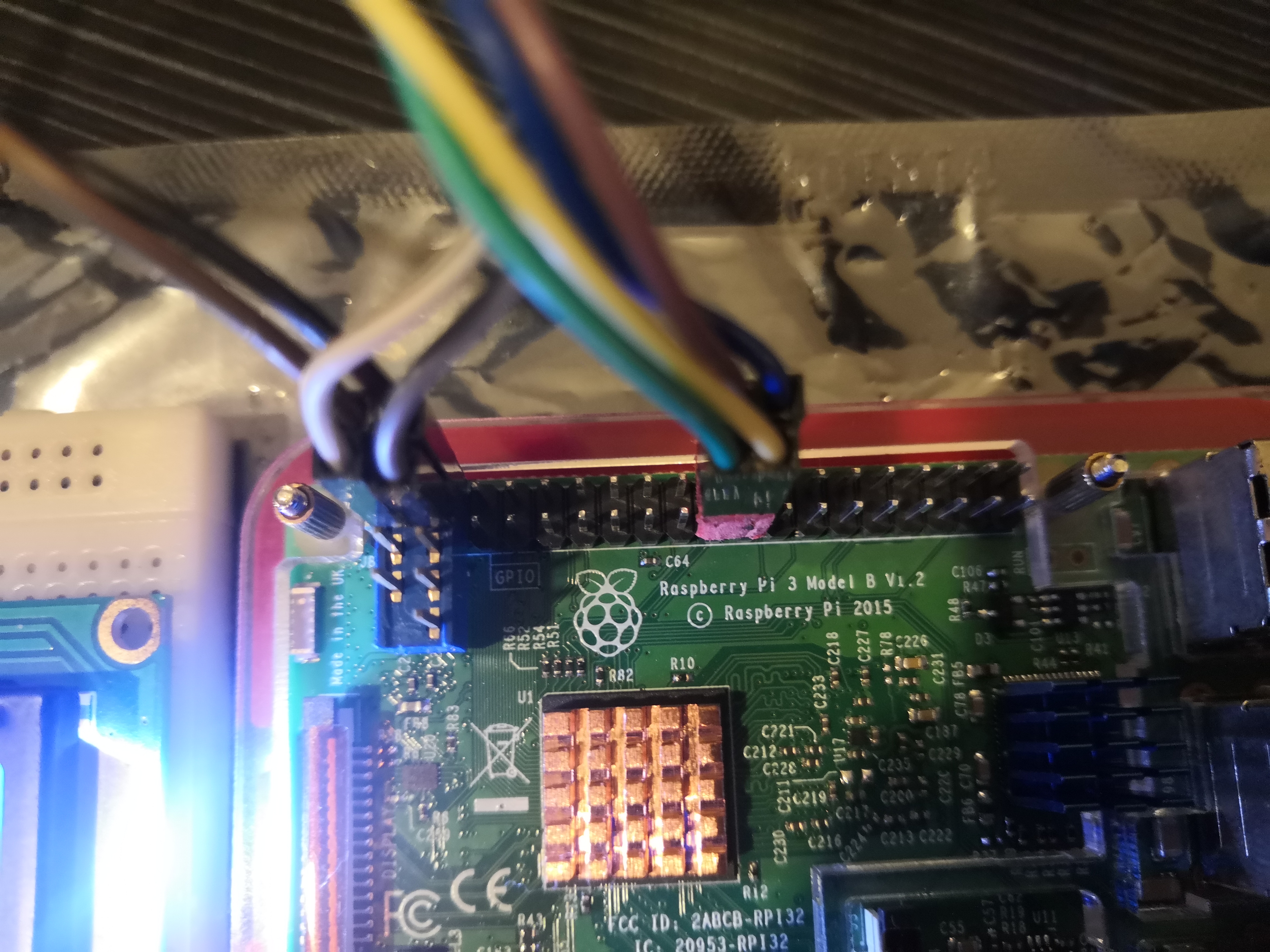
Para organizar mejor los cables he utilizado unos adaptadores de placa base para USB/Firewire que he cortado y adaptado, así que nos quedarán 2 grupos: el rojo para los datos y el azul para alimentación, RS y E.
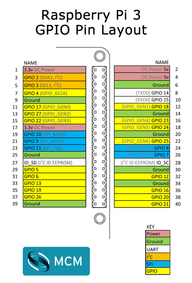
La numeración que seguiremos será la GPIO, para ello estableceremos el modo BCM con GPIO.setmode(BCM). Por ejemplo, en modo BCM el pin E sería 3 (GPIO3), en modo BOARD el pin E sería el 5 como se puede observar en la siguiente imagen.
Y ahora el código! hay que instalar los siguientes paquetes para poder ejecutar el script python:
sudo apt-get install python-setuptools

sudo apt-get install python-pip

sudo pip install rpi.gpio
Mostrando el Lorem Ipsum con scroll (dinámico) o mensaje estático (comentado)
#!/usr/bin/python

import RPi.GPIO as GPIO
from time import sleep

class HD44780:

        '''
        Inicializador
        '''
        def __init__(self):
                #Establecer pines GPIO de la Raspberry Pi para los pines RS, E y datos
                self.pin_rs = 2
                self.pin_e = 3
                self.pins_db = [25, 8, 9, 11]
                self.dinamico = False                   #Modo estático activado (el texto aparece escrito instantáneamente)

                #Establecer los pines como salida
                GPIO.setmode(GPIO.BCM)                  #Numeración BCM (numeración GPIO en lugar de numeración física de la placa)
                GPIO.setup(self.pin_e, GPIO.OUT)	#Establecer pin Enable como salida
                GPIO.setup(self.pin_rs, GPIO.OUT)	#Establecer pin Commando/Dato como salida
                for pin in self.pins_db:                #Establecer pines de datos como salida
                        GPIO.setup(pin, GPIO.OUT)

                self.clear()                            #Llamar a función local para vaciar la pantalla y setearla


        '''
        Vaciar pantalla y configurarla
        '''
        def clear(self):
                self.cmd(0x28) # Function set: Modo 4 bits, 2 líneas, 5x7 pixels (DL = 0: 4 bits, N = 1: 2 lines, F = 0: 5x7 dots, # = 0: Not 24x4 module)
                self.cmd(0x0C) # Display ON/OFF Control: Display activado, cursor y parpadeo desactivado (D = 1: Display On, C = 0: Cursor Off, B: Cursor blink off)
                self.cmd(0x06) # Entry Mode Set: Dirección del cursor (I/D = 1: Increment, S = 0: Do not accompany display shift)
                self.cmd(0x01) # Clear Display: Vaciar pantalla


        '''
        Enviar comando
        bits: comando a enviar
        char_mode: modo comando/dato. Por defecto en false (comando)
        '''
        def cmd(self, bits, char_mode=False):
                sleep(0.001)                            #Esperar 1ms
                bits = bin(bits)                        #Castear a binario
                bits = bits[2:]                         #Descartar los primeros 2 bits (0b)
                zeros = (8 - len(bits)) * "0"   	#Generar "00"
                bits = zeros + bits                     #Insertar los dos "00" a la izquierda de bits

                GPIO.output(self.pin_rs, char_mode)	#Establecer pin RS = modo comando / modo dato

                #Primer paquete
                self.inicializarDatos()                 #Inicializar datos a 0

                for i in range(4):                      #Se envian los datos, de 0 a 3
                        if bits[i] == "1":
                                GPIO.output(self.pins_db[::-1][i], True)        #Enviar solo los 1, los demás son 0 por defecto

                self.refrescarEnable()          #Refrescar enable

                #Segundo paquete
                self.inicializarDatos()         #Inicializar datos a 0

                for i in range(4, 8):           #Se envian los datos, de 4 a 7
                        if bits[i] == "1":
                                GPIO.output(self.pins_db[::-1][i-4], True)      #Enviar solo los 1, los demás son 0 por defecto

                self.refrescarEnable()          #Refrescar enable


        '''
        Mensaje a enviar (Soporte para cadenas con y sin salto de linea \n incluido)
	text: texto a enviar en string
	dinamico: modo dinámico. Por defecto en false (estático)
        '''
        def message(self, text, dinamico=False):
                self.dinamico = dinamico
                caracter = 0                                    #Contador de caracter (0 a 31)

                for i in range(len(text)):
                        if text[i] == '\n':                     #Salto de línea explícito
                                self.cmd(0xC0)                  #Segunda línea (Mover cursor a posición 0x40)

                        if self.dinamico:
                                if caracter == 16:              #Salto de linea implícito
                                        self.cmd(0xC0)          #Segunda línea (Mover cursor a posición 0x40)
                                elif caracter == 31:            #Fin de la segunda línea
                                        self.cmd(0x0F)          #Poner cursor parpadeando
                                        sleep(3)                #Esperar 3 segundos
                                        self.cmd(0x0C)          #Segunda linea y quitar cursor parpadeando
                                        self.cmd(0x01)          #Borrar display y cursor a home
                                        caracter = 0            #Resetear contador de caracter

                        if text[i] != '\n':                     #Enviar caracter si no es un salto de línea
                                self.cmd(ord(text[i]), True)

                        caracter += 1                           #Incrementar contador de caracter


        '''
        Inicializar datos
        '''
        def inicializarDatos(self):
                for pin in self.pins_db:
                        GPIO.output(pin, False)     #Inicializar todos los pines de datos a 0


        '''
        Refrescar enable
        '''
        def refrescarEnable(self):
                if(self.dinamico):
                        sleep(0.01)		    #Esperar 10ms solo en modo dinamico

                GPIO.output(self.pin_e, True)       #Enable = 1

                if(self.dinamico):
                        sleep(0.01)	            #Esperar 10ms solo en modo dinamico

                GPIO.output(self.pin_e, False)      #Enable = 0

                if(self.dinamico):
                        sleep(0.01)		    #Esperar 10ms solo en modo dinamico

'''
Función principal
'''
if __name__ == '__main__':
        lcd = HD44780()         #Cargar clase principal
	#lcd.clear()
        #lcd.message("   Welcome to\nUltimateRaspbian")		#Mensaje estático
        lcd.message("Lorem ipsum dolor sit amet, consectetur adipiscing elit. Nullam metus justo, eleifend et quam eget, congue consectetur lacus", True)	#Mensaje dinámico
        GPIO.cleanup()
He necesitado leer el datasheet del LCD HD44780 https://www.sparkfun.com/datasheets/LCD/HD44780.pdf para asegurarme del voltaje, lo que hace cada pin, qué comandos enviar para configurarlo a mi manera, etc.
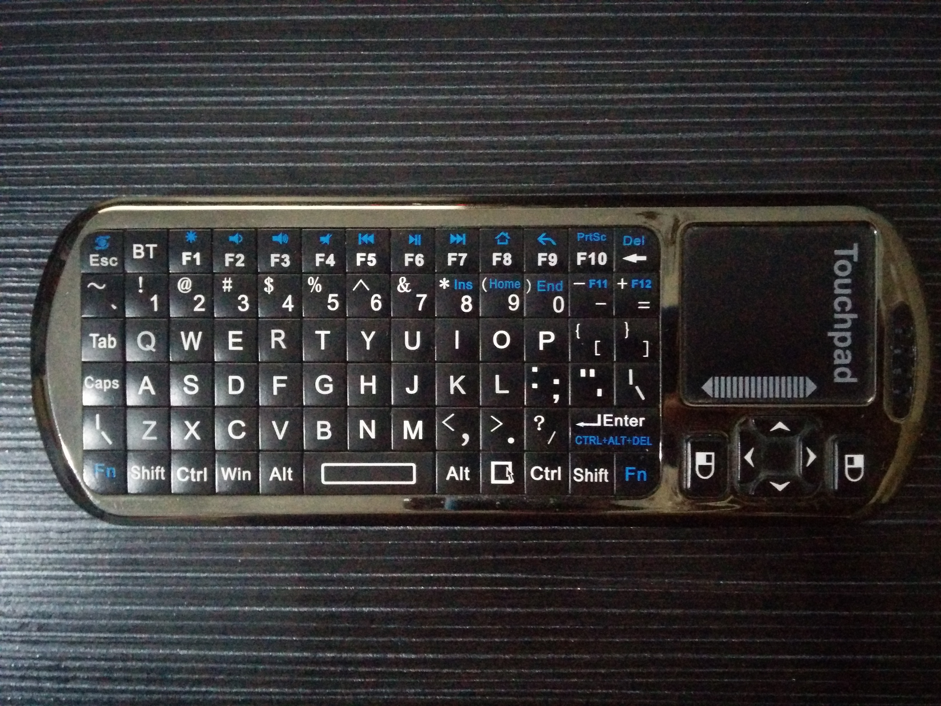
I’m going to pair my bluetooth keyboard+touchpad (Bluetooth iPazzPort), i’ll use the bluetoothctl tool.
First we’ll install the required packages with the folllowing command: sudo apt-get install pi-bluetooth bluez bluez-tools
We’ll start bluetoothctl -a in order to enter the program. Here i had a problem with the bluetooth daemon (the systemctl status bluetooth command returned an execution error), so i had to change permissions to this file with the following command: sudo chmod +x /usr/lib/bluetooth/bluetoothd
Now we’ll execute all these commands:
power on <- Powering on the controller
agent KeyboardOnly <- Setting the pairing mode
default-agent <- Setting the default agent
pairable on <- Viewable and pairable
scan on <- Enabling scanning
pair XX:XX:XX:XX:XX:XX <- Pairing with XX:XX:XX:XX:XX:XX


 Null Games